The armature generates 40 V when running at a speed of 400 rpm. This is shown in Equation 7. bldc motor design calculations.
Bldc Motor Design Calculations, Can you also tell me the design of this 45kw bldc motor controller please I shell be thankfull. TPS62152-Q1 is a step-down converter with 3-V to 17-V Input and output current up to 1 A. Fundamental Physics Electric motors transform power from the electrical domain to the mechanical domain using magnetic interaction.
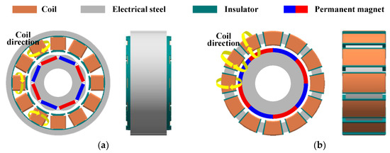 Processes Free Full Text A Study On A Slotless Brushless Dc Motor With Toroidal Winding Html From mdpi.com
It can help me for my project to help nature. Back-EMF calculation with respect to the number of sliced regions. Can you also tell me the design of this 45kw bldc motor controller please I shell be thankfull.
6 is coming from 6 step commutation in the controller.
Back-EMF calculation with respect to the number of sliced regions. 6 is coming from 6 step commutation in the controller. LM5060-Q1 is a high-side protection controller with controlled output rise time. 3602 6 pole pairs number. You can accomplish this in different ways such as. The design of a small-sized slotless BLDC motor.
Another Article :

This is shown in Equation 7. A BLDC generator for energy-harvesting was designed to produce 50-200 watts at shaft speeds of 500-1300 rpm. Through numerical analysis the basic dimensions are ascertained and the winding features are determined. How to calculate new dc motor parameters of a modified winding. At each point selected for calculation the efficiency η of the motor is the mechanical power output divided by the electrical power input. How Brushless Motor And Esc Work Howtomechatronics Electronics Projects For Beginners Free Energy Projects Free Energy.

Ttr its the time it takes to go 60 electrical degrees or 16 electrical period electrical frequency 16 ttr multiply by 2xpi to get rds multiply by number of pole pairs P to get mechanical speed multiply electrical frequency by 60xP to get RPM. This means the magnetic field generated by the stator and the magnetic field generated by the rotor rotate at the same frequency. The design equations and results such as Projected 3D views Flux patterns and Cogging torque are presented for 27 slots 8 pole and 075kW PMBLDCM. 6 is coming from 6 step commutation in the controller. Dc servomotor users sometimes find themselves with the right motor envelope but the wrong winding characteristics for. Brushless Dc Motors Introduction For Next Generation Missile Actuation Systems Outline Analog Devices.
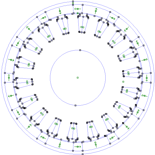
Brushless DC Motor Design and Build. A DC motor is connected to a source of 150 V and its armature resistance is 075 Ohms. Combining various methods to achieve the desired result. For BLDC motor drive applications. Through numerical analysis the basic dimensions are ascertained and the winding features are determined. Outer Rotor Bldc Motor With Surface Mounted Magnets.
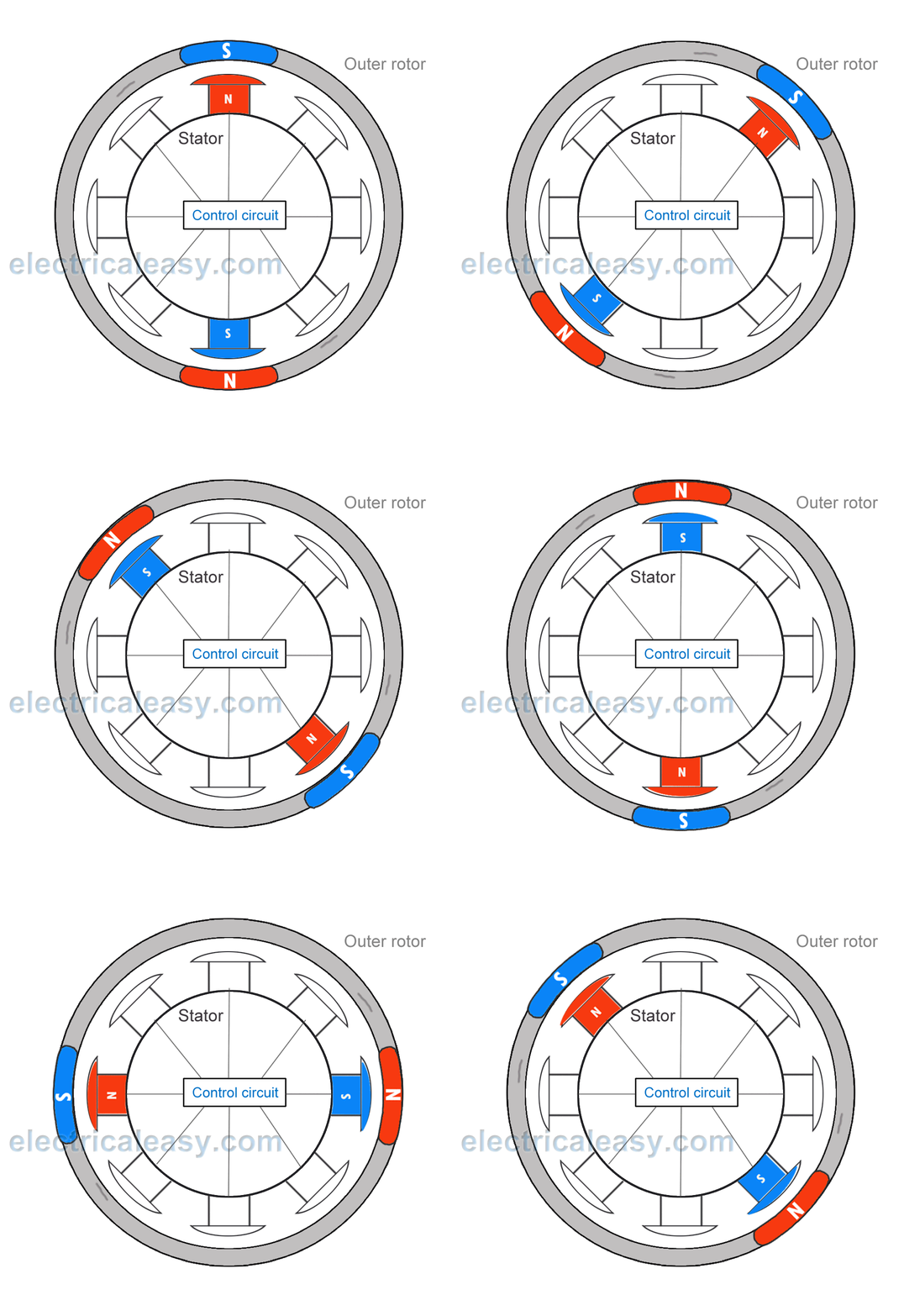
MOTOR DESIGN METHODOLOGY The design methodology of the three phase induction motor can be divided into the following processes. May 15 2020 by masuzi. The main design difference between a brushed and brushless motors is the replacement of mechanical commutator with an electric switch circuit. What I have been unable to find is an online calculator. The proposed BLDC motor is designed and simulated using FEA based design software tool MotorSolve. Brushless Dc Bldc Motor Construction And Working Electricaleasy Com.

Keeping that in mind a BLDC Motor is a type of synchronous motor in the sense that the magnetic field generated by the stator and the rotor revolve at the same frequency. 2 The back emf. 6 is coming from 6 step commutation in the controller. How to estimate the torque of a BLDC PMSM electric motor using only its Kv and current draw. Can you also tell me the design of this 45kw bldc motor controller please I shell be thankfull. Pdf Design Analysis And Fabrication Of A Brush Less Dc Motor.

6 is coming from 6 step commutation in the controller. BLDC motors do not experience the slip that is normally seen in induction motors. There exists a fundamental relationship between an electric motors velocity constant KV K V armature current IA I A and torque τ τ. For larger diameter andor motors that rotate more slowly a higher slot and pole count can be used such as 24s26p with a reduced number of turns per tooth and thinner Fe-Si laminations. A permanent-magnet 3-phase brushless DC electric motor is attached to a load. Processes Free Full Text A Study On A Slotless Brushless Dc Motor With Toroidal Winding Html.

Electric and magnetic loading calculation 5. Brushless Dc Motor Winding Calculation. At each point selected for calculation the efficiency η of the motor is the mechanical power output divided by the electrical power input. BLDC motors do not experience the slip that is normally seen in induction motors. A BLDC generator for energy-harvesting was designed to produce 50-200 watts at shaft speeds of 500-1300 rpm. Winding Layout Of A 9 Slots 8 Poles Bldc Machine With Non Overlapping Download Scientific Diagram.
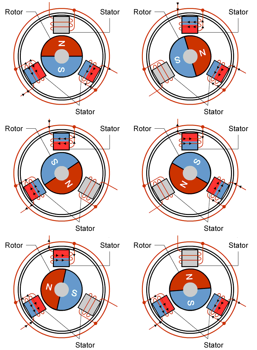
TPS62152-Q1 is a step-down converter with 3-V to 17-V Input and output current up to 1 A. BLDC motors come in single-phase 2-phase and 3-phase configurations. TPS62152-Q1 is a step-down converter with 3-V to 17-V Input and output current up to 1 A. For larger diameter andor motors that rotate more slowly a higher slot and pole count can be used such as 24s26p with a reduced number of turns per tooth and thinner Fe-Si laminations. A BLDC generator for energy-harvesting was designed to produce 50-200 watts at shaft speeds of 500-1300 rpm. Step 5 Motor Selection The Uav Chronicles.
Case study is our Razor scooter hub motor a BLDC motor designed inside a 5 diameter wheel. Measured efficiency at maximum power is 81. Equivalent circuit calculation 6. Through numerical analysis the basic dimensions are ascertained and the winding features are determined. In a BLDC motor this magnetic interaction occurs between coils of wire. Cross Section Of The Analyzed Two Pole Slotless Bldc Motor Only The Download Scientific Diagram.

A permanent-magnet 3-phase brushless DC electric motor is attached to a load. A BLDC generator for energy-harvesting was designed to produce 50-200 watts at shaft speeds of 500-1300 rpm. Main dimension calculations Stator OD ID and stack length 2. You can accomplish this in different ways such as. τ 83 I A KV τ 83 I A K V. Processes Free Full Text A Study On A Slotless Brushless Dc Motor With Toroidal Winding Html.

For larger diameter andor motors that rotate more slowly a higher slot and pole count can be used such as 24s26p with a reduced number of turns per tooth and thinner Fe-Si laminations. τ 83 I A KV τ 83 I A K V. The design equations and results such as Projected 3D views Flux patterns and Cogging torque are presented for 27 slots 8 pole and 075kW PMBLDCM. The armature generates 40 V when running at a speed of 400 rpm. A BLDC generator for energy-harvesting was designed to produce 50-200 watts at shaft speeds of 500-1300 rpm. 45kw Bushless Motor Design Brushless Motors 3phase Inverters Schematics.

Ttr its the time it takes to go 60 electrical degrees or 16 electrical period electrical frequency 16 ttr multiply by 2xpi to get rds multiply by number of pole pairs P to get mechanical speed multiply electrical frequency by 60xP to get RPM. Ttr its the time it takes to go 60 electrical degrees or 16 electrical period electrical frequency 16 ttr multiply by 2xpi to get rds multiply by number of pole pairs P to get mechanical speed multiply electrical frequency by 60xP to get RPM. December 6 2021 by masuzi. Combining various methods to achieve the desired result. A BLDC generator for energy-harvesting was designed to produce 50-200 watts at shaft speeds of 500-1300 rpm. A Novel Technique For Two Phase Bldc Motor To Avoid Demagnetization Semantic Scholar.

This means the magnetic field generated by the stator and the magnetic field generated by the rotor rotate at the same frequency. 45kw bushless motor design brushless poles bldc machine with non overlapping brushless dc motor inside solidworks stator winding design considerations. 3602 6 pole pairs number. The power dissipated calculations only rely on operation conditions. Through numerical analysis the basic dimensions are ascertained and the winding features are determined. Pdf Design And Modelling Of Bldc Motor For Automotive Applications Semantic Scholar.

TPS40210-Q1 is a current-mode boost controller with 45-V to 52-V input. The proposed BLDC motor is designed and simulated using FEA based design software tool MotorSolve. - Hall sensor table for a BLDC motor will be similar to the table below for 120deg hall sensor. Utilized as design objectives and constraints. LM5060-Q1 is a high-side protection controller with controlled output rise time. Hdd Bldc Motor.
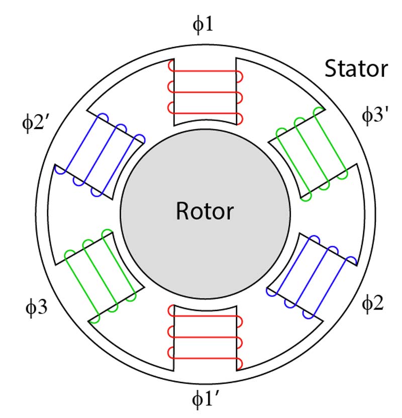
There exists a fundamental relationship between an electric motors velocity constant KV K V armature current IA I A and torque τ τ. Performance curve xc xlsx brushless dc motor control made easy best concrete design excel spreadsheet electrical ms excel spreadsheets. Performance Curve Xc Xlsx Brushless Dc Motor Control Made Easy. How to calculate new dc motor parameters of a modified winding. TPS40210-Q1 is a current-mode boost controller with 45-V to 52-V input. Choosing Between Brush And Brushless Dc Motors Allied Motion.


