X To find out the natural frequency of bevel gear and pinion mechanism. A diagram shows the curves of safety factors and life expectancy as function of torque. bevel gear design calculation pdf.
Bevel Gear Design Calculation Pdf, Tooth dimensions of spriral bevel gears according to ANSIAGMAISO standards 3 4 7. These are de- fined at the nominal center distance for the gearset as cut. Additional parts will be added continuously.
 Pdf Design And Analysis Of A Spiral Bevel Gear Semantic Scholar From semanticscholar.org
DESIGN OF BEVEL GEARS Bevel gears are designing for which calculating the required traction force and for keep ing a system compact bevel gears are designed by minimum requirement number of teeth. These are de- fined at the nominal center distance for the gearset as cut. Within the series of standards ISO10300 for the load carrying capacity calculation of bevel gears actually are covered standards for the tooth flank pitting and tooth root capacity.
Pressure angles of gearsets are standardized at a few values by the gear manufacturers.
Gear theory terminology selection of gear size tooth design parameters and cutting methods. Module and Diametral Pitch are reciprocal values. KMBSG2-4020R should mate with KMBSG2-2040L. They can be cut with either straight teeth where the same comments as for spur gears apply or they can be cut spiral which correspond to the helical type of parallel gearing. A diagram shows the curves of safety factors and life expectancy as function of torque. Within the series of standards ISO10300 for the load carrying capacity calculation of bevel gears actually are covered standards for the tooth flank pitting and tooth root capacity.
Another Article :

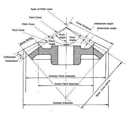
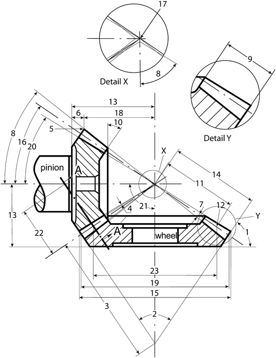
Bevel gears are used for drives requiring the input shaft to be at an angle usually 90 to the output shaft. Calculation of gear ratio i and pitch angle Selection of material. 20 for the nomenclature of a meshed bevel gear. Load calculation of gears 233 113 Calculation of load on spiral bevel gears In the case of spiral bevel gears the magnitude and direction of loads at the meshing point vary depending on the running direction and gear twist direction. Strength Calculation The safety margins against root fatigue fracture pitting and seizure are determined in the strength calculation acc. Bevel Gears Roy Mech.

The number of teeth in pinion can be assumed to be 20. Input Parameters Gear type - according to the position of root and head cone Gear ratio and tooth numbers Pressure angle the angle of tool profile α t Helix angle β m Axis angle Σ Tangential module on outer cone met for metric calculation Tangential Diametral Pitch on outer cone Pet for English units Note. A diagram shows the curves of safety factors and life expectancy as function of torque. This PPT contains 1. The number of teeth in pinion can be assumed to be 20. Fundamentals Of Bevel Gears Springerlink.

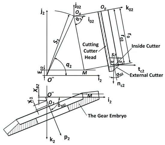
The objective of this project was to develop an automated process for modeling spiral bevel gears to reduce gear design time. Basic understanding of the design elements of bevel and hypoid gears. Tooth dimensions of spriral bevel gears according to ANSIAGMAISO standards 3 4 7. X To design and modeling of bevel gear and pinion assembly. The number of teeth in pinion can be assumed to be 20. Bevel Gear What Is It How Does It Work Types Uses.

The smallest gear is referred to as a pinion and the larger gear is referred to as gear. Select the diametral pitch with units of teeth per distance and then select the number of teeth for each. Introduction to Gear Design Introduction Albert Einstein once said. Load calculation of gears 233 113 Calculation of load on spiral bevel gears In the case of spiral bevel gears the magnitude and direction of loads at the meshing point vary depending on the running direction and gear twist direction. Things should be made as simple as possible but no simpler This book is an attempt to apply that principle to gear design by presenting information from a manufacturing point-of-view rather than a theoretical one. Design Of Bevel Gear I Youtube.

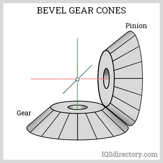
Pressure angles of gearsets are standardized at a few values by the gear manufacturers. Design a pair of bevel gear which is used to connect two shaft at right angles and transmit P 50 kW power from an induction motor to a conveyor belt. KHK stock bevel gears are available in two types spiral and straight tooth in gear ratios of 15 through 5 and are offered in a large va- riety of modules numbers of teeth materials and styles. These are de- fined at the nominal center distance for the gearset as cut. A bevel gear is shaped like a section of a cone. Concept Of Spiral Bevel Gear Hobbing Download Scientific Diagram.

Design of Bevel Gear - Free download as Powerpoint Presentation ppt pptx PDF File pdf Text File txt or view presentation slides online. Quick-View shows calculation results together with bevel gear drawings altogether on one screen. They can be cut with either straight teeth where the same comments as for spur gears apply or they can be cut spiral which correspond to the helical type of parallel gearing. The objective of this project was to develop an automated process for modeling spiral bevel gears to reduce gear design time. KMBSG2-4020R should mate with KMBSG2-2040L. Spiral Bevel Gear Forces Vortarus Technologies Llc.

The following table Table 1 is presenting the formulas t hat are used to calculate the blank and. Design of Bevel Gear - Free download as Powerpoint Presentation ppt pptx PDF File pdf Text File txt or view presentation slides online. A bevel gear is shaped like a section of a cone. These are de- fined at the nominal center distance for the gearset as cut. Pressure angles of gearsets are standardized at a few values by the gear manufacturers. Spiral Bevel Gear Forces Vortarus Technologies Llc.
Gear dimensions are determined in accordance with their specifications such as Module m Number of teeth z Pressureangle α and Profile shift coefficient x. For plastic bevel gears we recommend metal mating gears for good heat conductivity. But forCut straight tooth bevel gears there is some interchangeability with different series. It assumes 90 degree angle between the gears. To optimize the performance of any two bevel gears the gears must be positioned together so that they run smoothly without binding andor excessive backlash. Bevel Pdf Gear Mechanics.

Where NA and NB speed of the driver and driven respectively and ZA and ZB Number of teeth on driver and driven respectively. 20 for the nomenclature of a meshed bevel gear. A diagram shows the curves of safety factors and life expectancy as function of torque. Bevel gears can include straight spiral Zerol hypoid and. γ 1 γ 2 Σ γ 1 2 In case of a 90 shaft angle the relationship will simplify to. Applied Sciences Free Full Text Theoretical And Experimental Study On Contact Characteristics Of Spiral Bevel Gears Under Quasi Static And Large Loading Conditions Html.

The number of teeth in pinion can be assumed to be 20. A diagram shows the curves of safety factors and life expectancy as function of torque. 20 for the nomenclature of a meshed bevel gear. Input Parameters Gear type - according to the position of root and head cone Gear ratio and tooth numbers Pressure angle the angle of tool profile α t Helix angle β m Axis angle Σ Tangential module on outer cone met for metric calculation Tangential Diametral Pitch on outer cone Pet for English units Note. The design of a bevel gear starts from getting acquainted with various terminologies symbolsparameters and formulae attributed to Bevel gear. Helical Gear Calculations Crossed Helical Gear Meshes And Bevel Gearing Sdpsi.

X To design and modeling of bevel gear and pinion assembly. Basically KHK stock bevel gears should be selected as shown in the catalog in pairs eg. Input Parameters Gear type - according to the position of root and head cone Gear ratio and tooth numbers Pressure angle the angle of tool profile α t Helix angle β m Axis angle Σ Tangential module on outer cone met for metric calculation Tangential Diametral Pitch on outer cone Pet for English units Note. Bevel gears Bevel gears are useful when the direction of a shafts rotatidbhdion needs to be changed They are usually mounted on shafts that are 90 degrees apart b t can be designed to ork at otherdegrees apart but can be designed to work at other angles as well The teeth on bevel gears can beThe teeth on bevel gears can be straight spiral or hypoid. Bevel gears can include straight spiral Zerol hypoid and. Bevel Gearing Quality Transmission Components Pdf Catalogs Technical Documentation Brochure.

DESIGN OF BEVEL GEARS Bevel gears are designing for which calculating the required traction force and for keep ing a system compact bevel gears are designed by minimum requirement number of teeth. Pressure angles of gearsets are standardized at a few values by the gear manufacturers. X To design and modeling of bevel gear and pinion assembly. Input Parameters Gear type - according to the position of root and head cone Gear ratio and tooth numbers Pressure angle the angle of tool profile α t Helix angle β m Axis angle Σ Tangential module on outer cone met for metric calculation Tangential Diametral Pitch on outer cone Pet for English units Note. They can be cut with either straight teeth where the same comments as for spur gears apply or they can be cut spiral which correspond to the helical type of parallel gearing. Bevel Gears An Overview Sciencedirect Topics.

Basic understanding of the design elements of bevel and hypoid gears. Design of Bevel Gear - Free download as Powerpoint Presentation ppt pptx PDF File pdf Text File txt or view presentation slides online. Design procedure for Bevel Gear. Where NA and NB speed of the driver and driven respectively and ZA and ZB Number of teeth on driver and driven respectively. 20 for the nomenclature of a meshed bevel gear. Pdf Design And Analysis Of A Spiral Bevel Gear Semantic Scholar.

Design procedure for Bevel Gear. There are no great advances in gear technology described. Strength Calculation The safety margins against root fatigue fracture pitting and seizure are determined in the strength calculation acc. The sum of the pitch angles of spiral bevel gears is equal to the shaft angle. The design of a bevel gear starts from getting acquainted with various terminologies symbolsparameters and formulae attributed to Bevel gear. Pdf Design And Analysis Of A Spiral Bevel Gear Semantic Scholar.

Design a pair of bevel gear which is used to connect two shaft at right angles and transmit P 50 kW power from an induction motor to a conveyor belt. The following table Table 1 is presenting the formulas t hat are used to calculate the blank and. DESIGN OF BEVEL GEARS Bevel gears are designing for which calculating the required traction force and for keep ing a system compact bevel gears are designed by minimum requirement number of teeth. Design procedure for Bevel Gear. The smallest gear is referred to as a pinion and the larger gear is referred to as gear. Pdf Design And Analysis Of A Spiral Bevel Gear Semantic Scholar.


