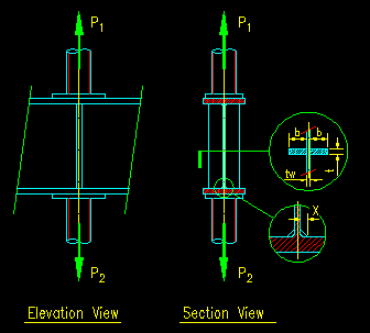
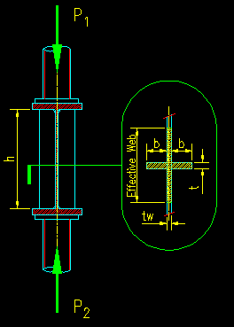
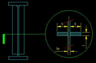
Design of end bearing stiffener in steel structure. Stiffener Bearing plate. bearing stiffener design example.
Bearing Stiffener Design Example, 8410 COMPARISON WITH FUNDAMENTAL MODE METHOD. 1 fy is yield stress of the stiffener and γM1 is partial resistance factor for the stability case. Calculators for structural engineers construction professionals and steel building specifiers.
 Pin On Structuraldetails Store Catalogue From pinterest.com
Nutte Structural 25 Jan 12 1135. Specifically web yielding web crippling and web buckling criteria are checked to determine if web stiffeners are required to resist the concentrated load. The pad eye thickness at the hole shall not be less than 75 the inside width of the shackle sect 16954 Rm 2 Rc1 2 Rc2 mm NOT OK 075 x e mm 4.
The total thicknesses of cheek plates on one side of the main plate should not exceed 100 sect 16955 of the main plate thickness.
Calculators for structural engineers construction professionals and steel building specifiers. Stiffener Design for Web Crippling. Design of Bearing stiffeners in accordance with CSA S16. For example in a ladder deck bridge the shear in the transverse beams will cause an axial force in the main beam stiffener. T 14 in. Try 10mm end plate and check bearing stiffener.
Another Article :

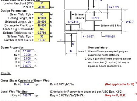
849 DESIGN ACTION EFFECTS FOR THE FOUNDATION. STIFFNER is a spreadsheet program written in MS-Excel for the purpose of analysis of steel beams subject to concentrated loads. But what I dont necessarily agree with is designing the plate to resist bending without considering the contribution of the flange. Design of end bearing stiffener in steel structure. The example is of a stiffened base plate. Baseplate Detail Steel Heb 240 Column Section Steel Columns Steel Trusses Concrete Footings.

This assumes that the spacing. SAMPLE CALCULATION Using AISI Wall Stud Design standard AISI S211-07 Calculate the nominal strength of a single deflection track subjected to transverse loads. Stiffener Design for Web Crippling. The example illustrates the design of a typical three-span continuous straight steel I-girder bridge with spans of 140-0 175-0 140-0. Conc rete deck steel plate girder bolted field splice shear connectors bearing stiffeners welded connections elastomeric bearing cantilever abutment and wingwall hammerhead pier and pile foundations. Steel Portal Frames Vertical Chs X Bracing Details Steel Columns Steel Trusses Steel Roofing.

If stiffeners are required the stiffener size and weld. The example illustrates the design of a typical three-span continuous straight steel I-girder bridge with spans of 140-0 175-0 140-0. Design of end bearing stiffener in steel structure. Stiffener Bearing plate. Design a stiffened seated connection between a W2168 beam and a W1490 column flange to support the following end reactions. Bearing Stiffeners.

Web Yielding Crippling Buckling and Stiffener Criteria for Concentrated Load or Reaction Per AISC 9th Edition Manual ASD. I would use 125tw each side of the outer stiffeners plus the web between the outer stiffeners and check it all as one combined section. 849 DESIGN ACTION EFFECTS FOR THE FOUNDATION. Illustrated through the design example. Reqd Connection Capacity to bottom flange P 2 - Capacity of W section. Steel Portal Frames Vertical Chs X Bracing Details Steel Trusses Roof Truss Design Steel Roofing.

Design of end bearing stiffener in steel structure. For example in a ladder deck bridge the shear in the transverse beams will cause an axial force in the main beam stiffener. Since Mtf Mq 6754 4565 The end panel can carry the bending moment. The web for example above a knuckle bearing which is providing torsional restraint to the main girder Tee stiffeners may be specified but this does add considerably to the task of welding and This example will illustrate the procedures to design a steel beam to BS 5400 Part 3. Published on February 7 2017. Bio Inspired Design Of Stiffener Plate Distribution In A Machine Tool Bed Download Scientific Diagram.

RD 21 kips RL 625 kips Use w in. To make this reference user-friendly the numbers and titles of the design steps are consistent between the. Stiffener Design for Web Crippling. N 19 in. Specifically web yielding web crippling and web buckling criteria are checked to determine if web stiffeners are required to resist the concentrated load. Baseplate Detail Steel Heb 240 Column Section Steel Columns Steel Trusses Concrete Footings.

RD 21 kips RL 625 kips Use w in. Reqd Connection Capacity to bottom flange P 2 - Capacity of W section. The web for example above a knuckle bearing which is providing torsional restraint to the main girder Tee stiffeners may be specified but this does add considerably to the task of welding and This example will illustrate the procedures to design a steel beam to BS 5400 Part 3. Illustrated through the design example. T 14 in. Bearing Stiffeners.

I 250156 3 12 10250 3 12 13110 6 mm 4 δ t 17442 3 320500013110 6 5110 -6 mmN. The plate and the flange will act like a T section. Since Mtf Mq 6754 4565 The end panel can carry the bending moment. Determine required plate thickness. Illustrated through the design example. Pin On Structuraldetails Store Catalogue.

A sample analytical method for bearing resistance calculation. In no case should the steel section be less than 00285L unless approved by the Bridge Design Engineer. T track thickness F ut track yield strength e design gap for deflection Ω 28 for ASD Φ 055 for LRFD F ut 045 for LSD α 10 when e t and stud spacing are. Stiffener plates can be applied to either just one side of the web or both sides. Design of steel bridges. Stiffner Steel Beam Web Stiffener Analysis Spreadsheet.

Typically a member taller than the minimum will be the most efficient. Typically a member taller than the minimum will be the most efficient. Illustrated through the design example. Design of steel bridges. 1 fy is yield stress of the stiffener and γM1 is partial resistance factor for the stability case. Bearing And Stiffener Design For Steel Beams Sd424 Youtube.

Conc rete deck steel plate girder bolted field splice shear connectors bearing stiffeners welded connections elastomeric bearing cantilever abutment and wingwall hammerhead pier and pile foundations. Yes I did. In no case should the steel section be less than 00285L unless approved by the Bridge Design Engineer. A A w 0 1 2 N Ed N Ed adjacent transverse stiffeners stiffener. Calculators for structural engineers construction professionals and steel building specifiers. Pin On Structuraldetails Store Catalogue.

Design a stiffened seated connection between a W2168 beam and a W1490 column flange to support the following end reactions. Diameter ASTM A325-N bolts in standard holes to connect the supported beam to the seat plate and top angle. Stiffener Bearing plate. For example in a ladder deck bridge the shear in the transverse beams will cause an axial force in the main beam stiffener. I 250156 3 12 10250 3 12 13110 6 mm 4 δ t 17442 3 320500013110 6 5110 -6 mmN. Web Stiffeners.

Specifically the example illustrates the design of selected critical sections from an exterior girder at the. To make this reference user-friendly the numbers and titles of the design steps are consistent between the. The plate and the flange will act like a T section. Partial depth stiffener are allowed. Published on February 7 2017. Design Of Stiffeners And Non Concentric Brace Connections With Risaconnection V3 Youtube.

If playback doesnt. Stiffener plates can be applied to either just one side of the web or both sides. These forces are shared between the two stiffener plates. Illustrated through the design example. The force to a single stiffener plate is half of the above. Steel Beam Design London Steel Beam Installation Steel Beams Beams Design.

To make this reference user-friendly the numbers and titles of the design steps are consistent between the. This will cater for situations where the load path from the bearing does not spread to the stiffener as a result of extreme thermal movement and. A sample analytical method for bearing resistance calculation. Nutte Structural 25 Jan 12 1135. STIFFNER is a spreadsheet program written in MS-Excel for the purpose of analysis of steel beams subject to concentrated loads. Advance Design Steel Connection.


