Annular snap joints. The most important are. ball joint design calculation.
Ball Joint Design Calculation, In the following the many design possibili-ties have been reduced to a few basic shapes. The ball joint can also be installed in linkage systems for motion control applications. Different approach for lattice girder joints For many types of joint configurations.
 Pdf Process Design Of A Ball Joint Considering Caulking And Pull Out Strength From researchgate.net
Real engineers check the sensitivity of their models to the factors in them. Maximum allowable torque at dowels Where A Dowel cross section area mm2. Annular snap joints.
If you told me that the calculation of wheel rate showed a significant contribution from ball joint radial stiffness I would laugh at you.
Figure 1- Tire longitudinal force. P St x As. In the following the many design possibili-ties have been reduced to a few basic shapes. Centrifugal Force Calculations of Rotating Body When gear rotates about any axis other than one at its center of mass it exerts an outward radial force called centrifugal force. ME EN 7960 Precision Machine Design Ball Screw Calculations 4-9 Fixed-Free Mount Source. This includes Applicable codes Reduced full bore design Soft Metal seated design Side Top Entry Welded body design Valve ends Valve operators Floating trunnion mounted design SPE DPE Body cavity relief features DBB DIB Extended bonnet weld overlay Anti static Fire safe design.
Another Article :

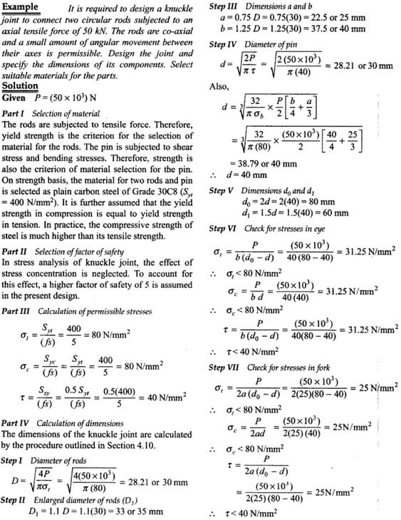
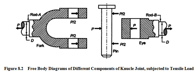
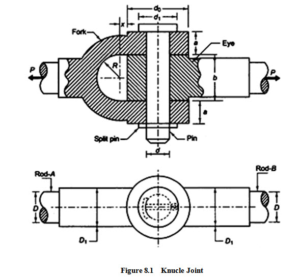
U-shaped snap joints A variation of the cantilever type. Real engineers check the sensitivity of their models to the factors in them. 3598 Plug Number of nodes. For this reason the tensile stress area is calculated through an empirical formula involving the nominal diameter of the fastener and the thread pitch. D dowel diameter mm. Machine Design Lesson 8 Design Of Knuckle Joint.

Calculation principles have been derived for these basic designs. The ball joint is made of a socket bearing plug and ball stud as. Dynamic model of the ball joint. Most commonly used mounting setup. The basic parameters used in ball mill design power calculations rod mill or any tumbling mill sizing are. Steering Knuckle An Overview Sciencedirect Topics.

The Final design used triangular pockets to. From maximum beam deflection and Snap structure we can also calculate the force required for assembly and disassembly of the cantilever snap joint. Centrifugal Force Calculations of Rotating Body When gear rotates about any axis other than one at its center of mass it exerts an outward radial force called centrifugal force. 2220 Number of elements. Ball Screw Design Equations and Selection Criteria A ball screw transforms rotational motion into transitional motion. Modeling The Angular Capability Of The Ball Joints In A Complex Mechanism With Two Degrees Of Mobility Sciencedirect.

17669 Bearing Number of nodes. Centrifugal Force Calculations of Rotating Body When gear rotates about any axis other than one at its center of mass it exerts an outward radial force called centrifugal force. When designing ball joints it is best to make them an exact fit where the positive part the ball and the negative part the socket are the exact same circumference. Torsion snap joints Shear stresses carry the load. The designers should be aware that the number of tire. Modeling The Angular Capability Of The Ball Joints In A Complex Mechanism With Two Degrees Of Mobility Sciencedirect.
Real engineers check the sensitivity of their models to the factors in them. From maximum beam deflection and Snap structure we can also calculate the force required for assembly and disassembly of the cantilever snap joint. This work describes a simulation strategy for a ball joint analysis considering the manufacturing process. 17669 Bearing Number of nodes. Dynamic model of the ball joint. 2.

The ball joint is made of a socket bearing plug and ball stud as. When designing ball joints it is best to make them an exact fit where the positive part the ball and the negative part the socket are the exact same circumference. D dowel diameter mm. The ball joint is made of a socket bearing plug and ball stud as. ME EN 7960 Precision Machine Design Ball Screw Calculations 4-9 Fixed-Free Mount Source. Machine Design Lesson 8 Design Of Knuckle Joint.

Cantilever snap joints The load here is mainly flexural. Joints considered as a whole Check of relevant failure modes Scope of application to be checked. The upper and lower ball joints and applied at the caliper mounting holes. Material to be ground characteristics Bond Work Index bulk density specific density desired mill tonnage capacity DTPH operating solids or pulp density feed size as F80 and maximum chunk size product size as P80 and maximum and finally the type of circuit openclosed you are. Effective matl ult 242ksi effective matl yeild 129ksi shank dia 196mm ball center 196mm shank dia. Propeller Shaft And Drive Shaft Automobile.
This includes Applicable codes Reduced full bore design Soft Metal seated design Side Top Entry Welded body design Valve ends Valve operators Floating trunnion mounted design SPE DPE Body cavity relief features DBB DIB Extended bonnet weld overlay Anti static Fire safe design. Calculation for Stem design with Ball joint using Dowel pins. ME EN 7960 Precision Machine Design Ball Screw Calculations 4-10 Fixed-Supported Mount Source. Different approach for lattice girder joints For many types of joint configurations. The most important are. 2.

H Ball Joint center to center length L Ball Joint Length 2 Elbow tangent lengths H 60 165 Column 6 of Dimension Data 2 x 15 long radius elbows 1065 without preset and H 30165 2 x 15 765 with preset. 18936 Number of elements. Axial loads shear loads thermal loads and thread tear out are used in factor of safety calculations. 2220 Number of elements. The Final design used triangular pockets to. Modeling The Angular Capability Of The Ball Joints In A Complex Mechanism With Two Degrees Of Mobility Sciencedirect.

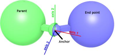
Specific loads at dowels SL Mt cdv21000 Calculation 7. The joint forces and moments for ball joints and bushings of a double wishbone suspension system are calculated with the proposed method in this article and compared with that obtained using two conventional methods method I and method II when. This work describes a simulation strategy for a ball joint analysis considering the manufacturing process. D dowel diameter mm. Real engineers check the sensitivity of their models to the factors in them. Webots Documentation Balljoint.

Joints considered as a whole Check of relevant failure modes Scope of application to be checked. The designers should be aware that the number of tire. Mm Applied to a 34-10 x 7 SAE J429 Grade 5 HCS. Real engineers check the sensitivity of their models to the factors in them. Guidance is provided for general bolted joint design computation of preload uncertainty and preload loss and the calculation of the bolted joint factor of safety. Analysis And Design Of A Ball Joint Considering Manufacturing Process Semantic Scholar.

5358 Number of elements. 0602 Regardless of the way it functions the bolt must be tightened properly in order for it to perform the intended function. The initial design of the ball joint is shown in Figure 1. In the first SLA example the loaded lower ball joint is located below the centerline of the wheel and the sprung weight of the vehicle is pressing down on the lower control arm. You need to ensure the socket component is not entirely enclosed more like a C shape to allow the part to expand slightly to snap it into place. Pdf Process Design Of A Ball Joint Considering Caulking And Pull Out Strength.

YS Yield strength of dowel MOC Nmm2. Cheers Greg Locock Please see FAQ731-376. A ball joint is an automobile component that connects control arm to knuckle part. Effective matl ult 242ksi effective matl yeild 129ksi shank dia 196mm ball center 196mm shank dia. Most commonly used mounting setup. Pdf Process Design Of A Ball Joint Considering Caulking And Pull Out Strength.

Material to be ground characteristics Bond Work Index bulk density specific density desired mill tonnage capacity DTPH operating solids or pulp density feed size as F80 and maximum chunk size product size as P80 and maximum and finally the type of circuit openclosed you are. The ball joint investigated in this research is a part that is connected to a knuckle and a lower control arm. In the first SLA example the loaded lower ball joint is located below the centerline of the wheel and the sprung weight of the vehicle is pressing down on the lower control arm. Ball Screw Design Equations and Selection Criteria A ball screw transforms rotational motion into transitional motion. Different approach for lattice girder joints For many types of joint configurations. Machine Design Lesson 8 Design Of Knuckle Joint.

Eurocodes - Design of steel buildings with worked examples Brussels 16 - 17 October 2014. 5358 Number of elements. The ball joint can also be installed in linkage systems for motion control applications. Guidance is provided for general bolted joint design computation of preload uncertainty and preload loss and the calculation of the bolted joint factor of safety. The upper and lower ball joints and applied at the caliper mounting holes. Analysis And Design Of A Ball Joint Considering Manufacturing Process Semantic Scholar.


