8214 Packet Tracer Designing and Implementing a VLSM Addressing Scheme Packet Tracer Designing and Implementing a VLSM Addressing Scheme Answer Version Answer Note. Design the VLSM Addressing Scheme Part 3. 82 14 designing and implementing a vlsm addressing scheme answers.
82 14 Designing And Implementing A Vlsm Addressing Scheme Answers, Examine the Network Requirements Part 2. Last Updated on January 31 2019 by Admin. Divide the 19216872024 network based on the number of hosts per subnet.
 8 2 1 4 Packet Tracer Designing And Implementing A Vlsm Addressing Scheme Packet Tracer Designing And Implementing A Vlsm Addressing Scheme Topology Course Hero From coursehero.com
8215 Lab Designing and Implementing a VLSM Addressing Scheme Answers Lab Designing and Implementing a VLSM Addressing Scheme Answers Version Answers Note. 8215 Lab Designing and Implementing a VLSM Addressing Scheme Answers Lab Designing and Implementing a VLSM Addressing Scheme Answers VersionAnswers Note. Design the VLSM Addressing Scheme Part 3.
Use the first subnet to accommodate the largest LAN.
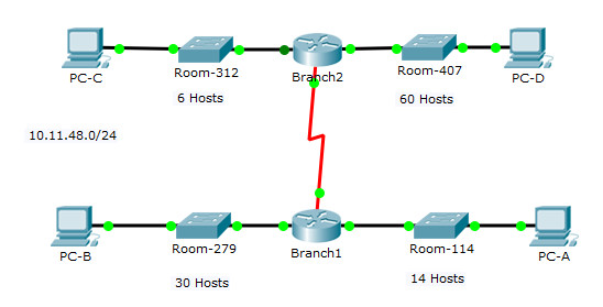
Red font color or gray highlights indicate text that appears in the Answer copy only. After you have designed the VLSM address scheme you will configure the interfaces on the routers with the appropriate IP address information. Optional activities are designed to enhance understanding andor to provide additional practice. Assign IP Addresses to Devices and Verify Connectivity Background In this activity you are given a 24 network address to use to design a VLSM addressing scheme. You will receive one of three possible topologies. 8214 Packet Tracer Designing and Implementing a VLSM Addressing Scheme.
Another Article :

Page 3 of 4 Packet Tracer - Designing and Implementing a VLSM Addressi ng Scheme Suggested Scoring Rubric Activity Section Part 1. Based on a set of requirements you will assign subnets and addressing configure devices and verify connectivity. Subnet 19216872024 into 19216872026. 8214 Packet Tracer Designing and Implementing a VLSM Addressing Scheme Packet Tracer Designing and Implementing a VLSM Addressing Scheme Answer Version Answer Note. 83 Design Considerations for IPv6 831 Subnetting an IPv6 Network 8311 The IPv6 Global Unicast Address. Ccnav6 S1 8 2 1 4 Packet Tracer Designing And Implementing A Vlsm Addressing Scheme.

Based on a set of requirements you will assign subnets and addressing configure devices and verify connectivity. Topology You will receive one of three possible topologies. 8215 Lab Designing and Implementing a VLSM Addressing Scheme Answers Lab Designing and Implementing a VLSM Addressing Scheme Answers VersionAnswers Note. 8214 Packet Tracer Designing and Implementing a VLSM Addressing Scheme. Last Updated on January 31 2019 by Admin. 8 2 1 4 Packet Tracer Designing And Implementing A Vlsm Addressing Scheme Packet Tracer Designing And Implementing A Vlsm Addressing Scheme Topology Course Hero.
Red font color or gray highlights indicate text that appears in the Answer copy only. Subnet 19216872024 into 19216872026. 8214 Packet Tracer Designing and Implementing a VLSM Addressing Scheme. Red font color or Gray highlights indicate text that appears in the instructor copy only. 8214 Packet Tracer Designing and Implementing a VLSM Addressing Scheme Packet Tracer Designing and Implementing a VLSM Addressing Scheme Answer Version Answer Note. Packet Tracer Designing And Implementing A Vlsm Addressing Scheme.
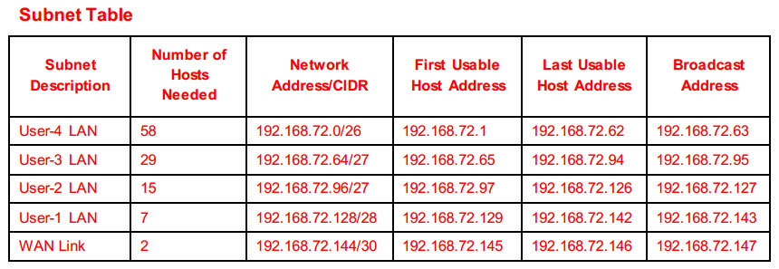
IPv6 subnetting is not concerned with conserving address space. Based on a set of requirements you will assign subnets and addressing configure devices and verify connectivity. Red font color or gray highlights indicate text that appears in the Answer copy only. Design the VLSM Addressing Scheme Complete Subnet Table 25 Document Addressing 40 Part 2. 8214 Packet Tracer - Designing and Implementing a VLSM Addressing Scheme - ILMpdf Note that the Device column is independent of the addressing scheme. 8 2 1 4 9 2 1 5 Packet Tracer Designing And Implementing A Vlsm Addressing Scheme Instructions Answers.
8214 Packet Tracer Designing and Implementing a VLSM Addressing Scheme Packet Tracer Designing and Implementing a VLSM Addressing Scheme Answer Version Answer Note. VLSM is used to meet the IPv4 addressing requirements. Topology You will receive one of three possible topologies. Based on a set of requirements you will assign subnets and addressing configure devices and verify connectivity. Red font color or gray highlights indicate text that appears in the Answer copy only. 8 2 1 4 9 2 1 5 Packet Tracer Designing And Implementing A Vlsm Addressing Scheme Instructions Answers.

8214 Packet Tracer Designing and Implementing a VLSM Addressing Scheme Packet Tracer Designing and Implementing a VLSM Addressing Scheme Answer Version Answer Note. Last Updated on January 14 2021 by Admin. Red font color or Gray highlights indicate text that appears in the instructor copy onlyOptional activities are designed to enhance. For example a student could receive the device names from Scenario 1 and the addressing scheme from Scenario 3. The largest LAN is ASW-4 with 58 hosts. 11 9 3 8 2 1 4 Designing And Implementing A Vlsm Addressing Scheme.

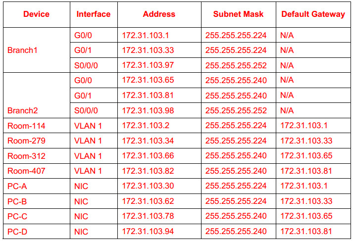
8215 Lab Designing and Implementing a VLSM Addressing Scheme. The largest LAN is ASW-4 with 58 hosts. Design the VLSM Addressing Schstronge Step 1. For example a student could receive the device names from Scenario 1 and the addressing scheme from Scenario 3. Addressing Table Device Interface. 8 2 1 4 Packet Tracer Designing And Implementing A Vlsm Addressing Scheme Packet Tracer Designing And Implementing A Vlsm Addressing Scheme Topology Course Hero.

8215 Lab Designing and Implementing a VLSM Addressing Scheme. 8214 Packet Tracer - Designing and Implementing a VLSM Addressing Scheme Based on a set of requirements you will assign subnets and addressing configure devices and verify connectivity. In this activity you are given a 24 network address to use to design a VLSM. The largest LAN is ASW-4 with 58 hosts. This will give us 4 subnets 22 4 with 64 hosts per. 8 2 1 5 9 2 1 4 Lab Designing And Implementing A Vlsm Addressing Scheme Youtube.

Addressing Table Device Interface. Subnet 19216872024 into 19216872026. Use the first subnet to accommodate the largest LAN. Examine the Network Requirements Question Location Possible Points Step 1 1 Step 2 4 Part 1 Total Earned Points 5 Part 2. Divide the 19216872024 network based on the number of hosts per subnet. Ccnav6 S1 8 2 1 4 Packet Tracer Designing And Implementing A Vlsm Addressing Scheme.

8214 Packet Tracer Designing and Implementing a VLSM Addressing Scheme Packet Tracer Designing and Implementing a VLSM Addressing Scheme Answer Version Answer Note. You will subnet the network address DisplayNet. This video shows the packet tracer activity Designing and implementing a VLSM addressing scheme. Design the VLSM Addressing Scheme Complete Subnet Table 25 Document Addressing 40 Part 2. 8214 Packet Tracer - Designing and Implementing a VLSM Addressing Schemepka 8215 Lab - Designing and Implementing a VLSM Addressing Scheme 8314 Packet Tracer - Implementing a Subnetted IPv6 Addressing Scheme. 8 2 1 4 Packet Tracer Designing And Implementing A Vlsm Addressing Scheme Youtube.

Topology You will receive one of three possible topologies. You may be offline or with limited connectivity. You will subnet the network address DisplayNet. Red font color or Gray highlights indicate text that appears in the instructor copy onlyOptional activities are designed to enhance. Red font color or gray highlights indicate text that appears in the Answer copy only. Packet Tracer Designing And Implementing A Vlsm Addressing Scheme Asw 2 Lan Course Hero.

8215 Lab Designing and Implementing a VLSM Addressing Scheme Answers Lab Designing and Implementing a VLSM Addressing Scheme Answers VersionAnswers Note. Assign IP Addresses to Devices and Verify Connectivity Background In this activity you are given a 24 network address to use to design a VLSM addressing scheme. This video shows the packet tracer activity Designing and implementing a VLSM addressing scheme. Design the VLSM Addressing Scheme Part 3. Last Updated on January 14 2021 by Admin. 11 9 3 8 2 1 4 Designing And Implementing A Vlsm Addressing Scheme.

Packet Tracer Designing and Implementing a VLSM Addressing Scheme Addressing Table. Last Updated on January 14 2021 by Admin. Red font color or Gray highlights indicate text that appears in the instructor copy onlyOptional activities are designed to enhance. 8214 Packet Tracer Designing and Implementing a VLSM Addressing Scheme Packet Tracer Designing and Implementing a VLSM Addressing Scheme Answer Version Answer Note. Addressing Table Device Interface. Packet Tracer Designing And Implementing A Vlsm Addressing Scheme.

8214 Packet Tracer Designing and Implementing a VLSM Addressing Scheme Packet Tracer Designing and Implementing a VLSM Addressing Scheme Answer Version Answer Note. VLSM is used to meet the IPv4 addressing requirements. 8214 Packet Tracer Designing and Implementing a VLSM Addressing Scheme Packet Tracer Designing and Implementing a VLSM Addressing Scheme Answer Version Answer Note. 8215 Lab Designing and Implementing a VLSM Addressing Scheme Answers Lab Designing and Implementing a VLSM Addressing Scheme Answers VersionAnswers Note. This video shows the packet tracer activity Designing and implementing a VLSM addressing scheme. 11 9 3 8 2 1 4 Designing And Implementing A Vlsm Addressing Scheme.
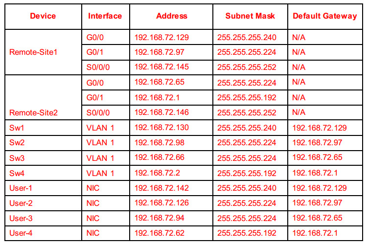
8214 Packet Tracer Designing and Implementing a VLSM Addressing Scheme Packet Tracer Designing and Implementing a VLSM Addressing Scheme Answer Version Answer Note. 8214 Packet Tracer Designing and Implementing a VLSM Addressing Scheme. Assign IP Addresses to Devices and Verify Connectivity. Use the first subnet to accommodate the largest LAN. Red font color or gray highlights indicate text that appears in the Answer copy only. 8 2 1 4 9 2 1 5 Packet Tracer Designing And Implementing A Vlsm Addressing Scheme Instructions Answers.


